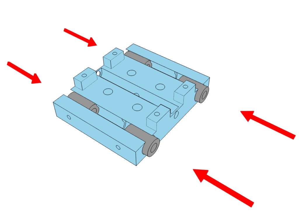
1. Insert 4 x linear bearings into the slots in the X Carriage bottom piece.
If a bearing doesn't fit snugly, put a single layer of tape evenly around it.
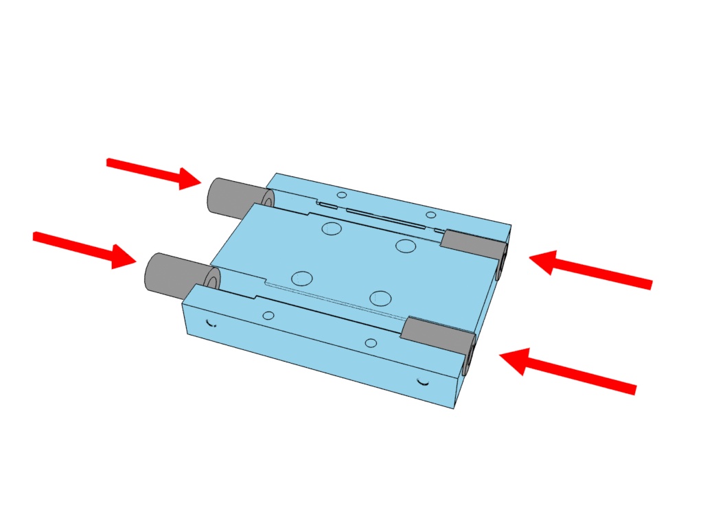

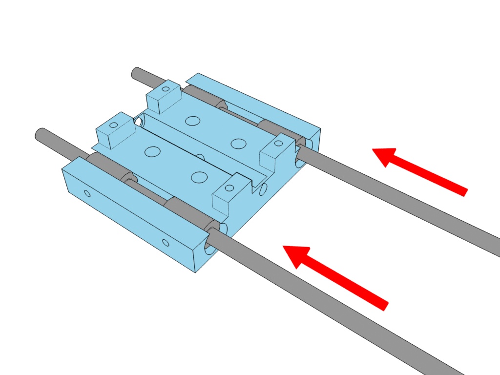
2. CAREFULLY insert the two 350mm linear rods through the bearings.
If the rods don't go in smoothly, rotate them slightly but don't force them as this can knock balls out from the bearing.
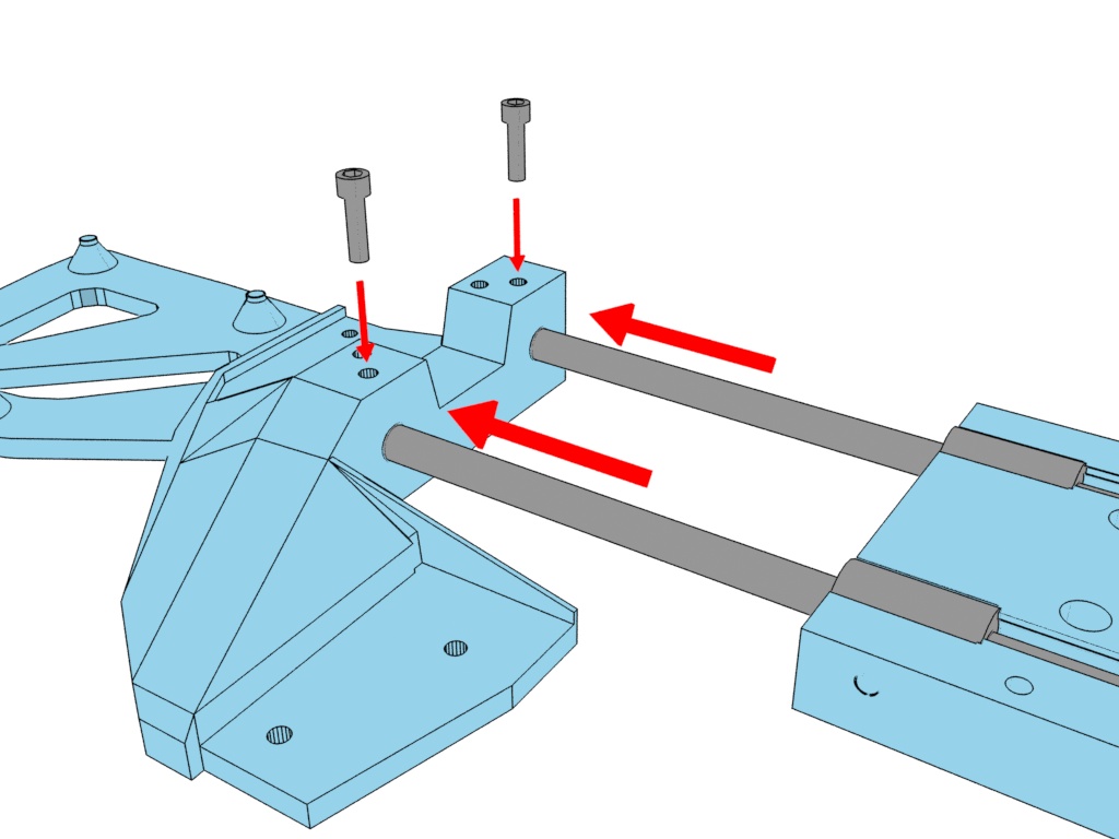
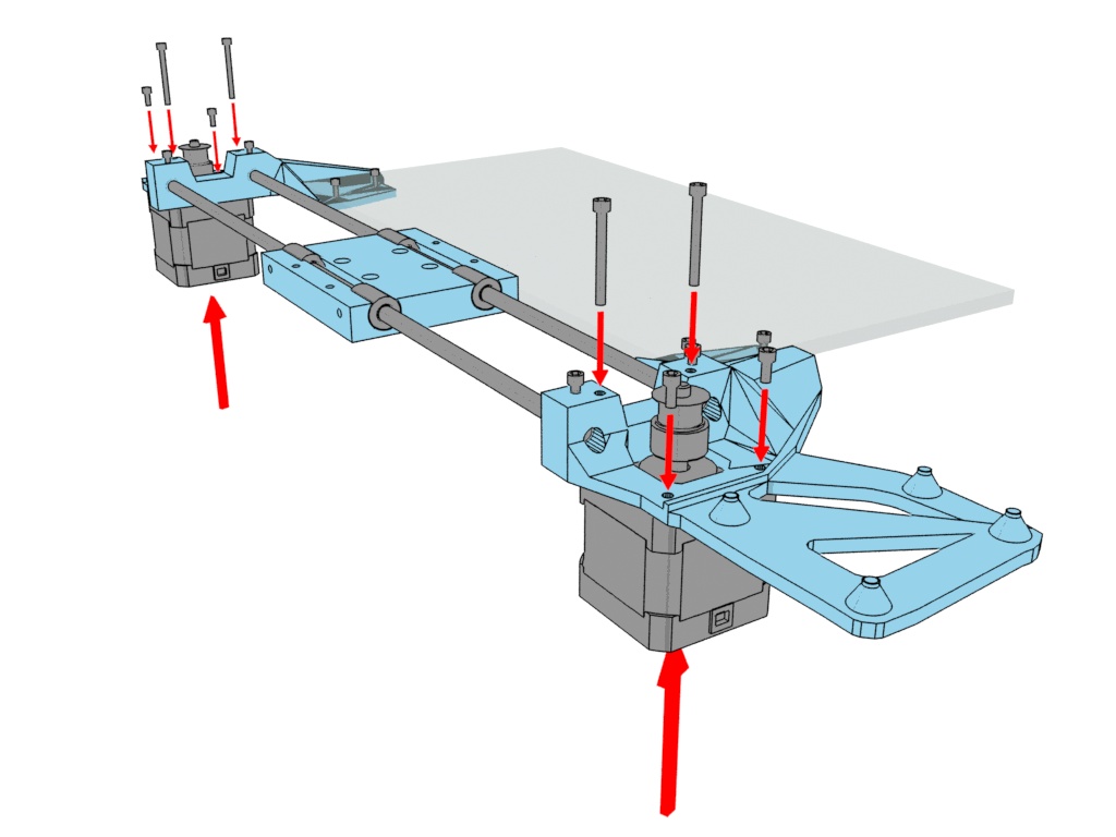
3. Insert the 350mm rods into the 6mm diameter holes in the left motor mount.
This may require a little force, feel free to tap the rods in with a hammer... carefully.
Carefully screw in the 10mm lock screws, being careful to stop once they hit the rods. They only need to touch the rods to prevent them moving, tightening them too much will drill out the holes.

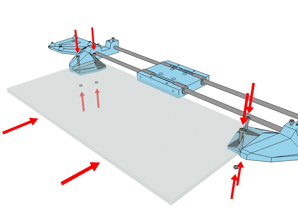
4. Insert the opposite ends of the 350mm rods in to the 6mm diameter into the right motor mount, same as with the left.
The plastic is strong enough to handle a few well placed taps with a hammer if necessary.
5. Move the acrylic sheet into place between the two mounts, make sure the right mount is pushed onto the rods far enough that the holes line up.
Use 4 M3 12mm screws and M3 nuts to hold the acrylic to the mounts, be sure they are nice and tight.
6. Insert 4 x linear bearings into the X carriage top piece.
If a bearing doesn't fit snugly, put a single layer of tape evenly around it.
7. Insert the 250mm rods through the linear bearings, being careful again not to knock any balls out.

8. Being mindful of their correct orientation, insert the two ends of the Y assembly onto the linear rods. This may need the hammer again.
Check again to make sure it looks the same as in the picture, you're going to feel silly if you put a piece in upside down.
Screw in the 10mm lock screws, being careful to stop once they touch the rods.
9. Attach the left and right stepper motors with the wires or plugs facing to the left. Screw in with 4 x M3 25mm screws and 4 x M3 6mm screws.

10. Insert 4 x M6 40mm screws from the bottom of the X Carriage bottom piece. On each screw insert an M6 washer, bearing and another M6 washer.
Friction should be enough to hold them for now but if not use a few pieces of tape on the bottom to hold them temporarily.
11. Place the belt as pictureed.


12. Lower the Y assembly onto the 4 M6 bolts, being careful that the belt stays in place. Finger tighten 4 M6 nuts, don't make them too tight otherwise the bearings won't turn freely.
13. Prepare a bearing with an M6 washer on the top and bottom. Place the bearing in the belt loop and place it within the Y end cap. Fix it in place with an M6 bolt and nut but not too tight that the bearing can't spin freely.
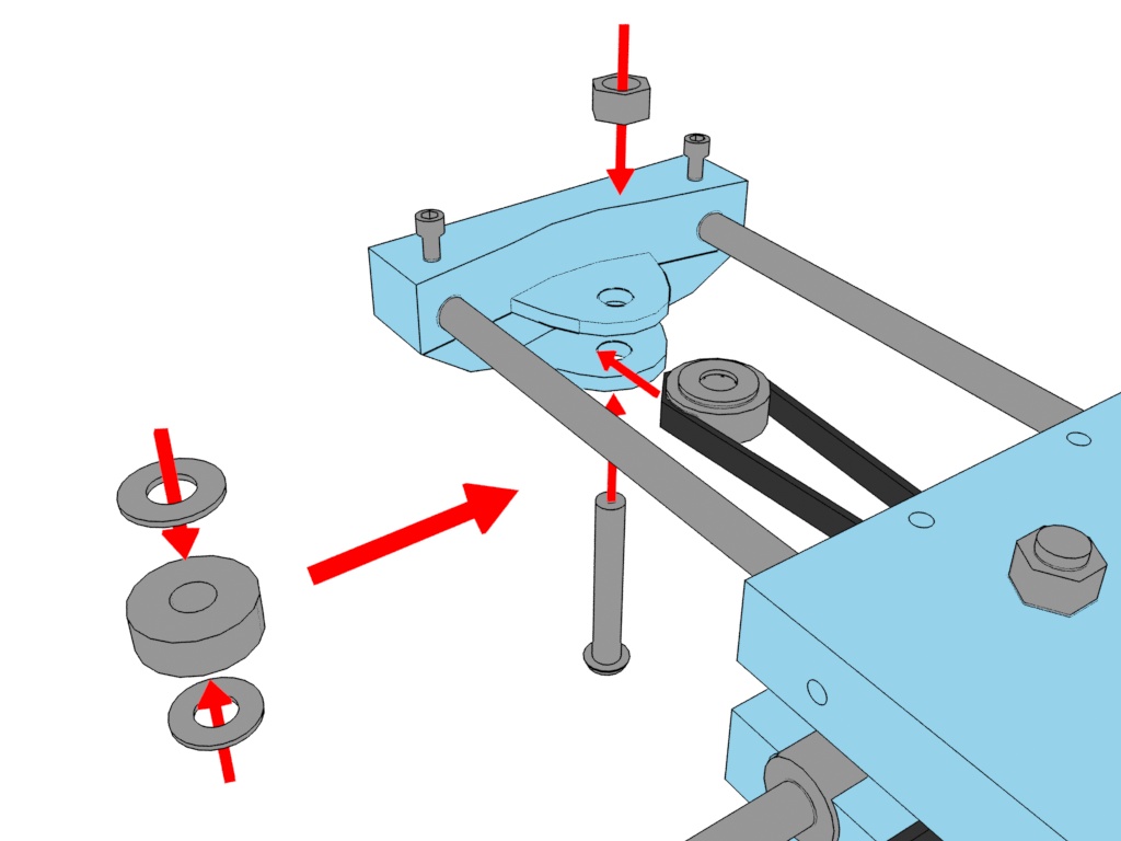
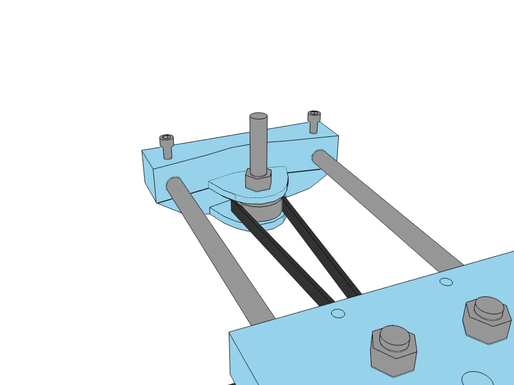
14. It should look like this.
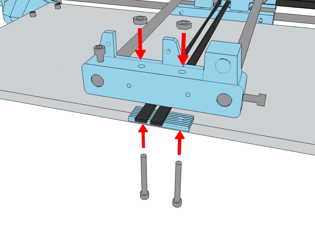
15. Hold the belt clamp in place with 2 x M3 25mm screws and nuts. Before tightening the belt clamp pull the belt as tight as possible by clamping and twisting them with a pair of pliers.
The belt should be very tight.
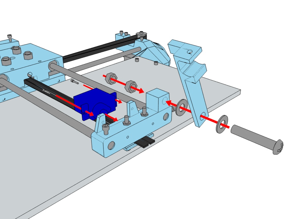
16. Fix the servo in place with the provided self tapping screws.
Attach the tool holder with a M6 30mm bolt, 2 x M6 washers and 2 x M6 nuts. Tighten the nuts until the tool holder no longer raises and falls freely and then loosen it slightly. The tool holder should rotate freely but be sandwiched between the washers tight enough that it doesn't wobble.
17. Insert a M3 10mm screw and M3 nut into the tool holder.
Fix the servo horn on with the provided screw, don't tighten it too much at this point as it may need adjustment later.

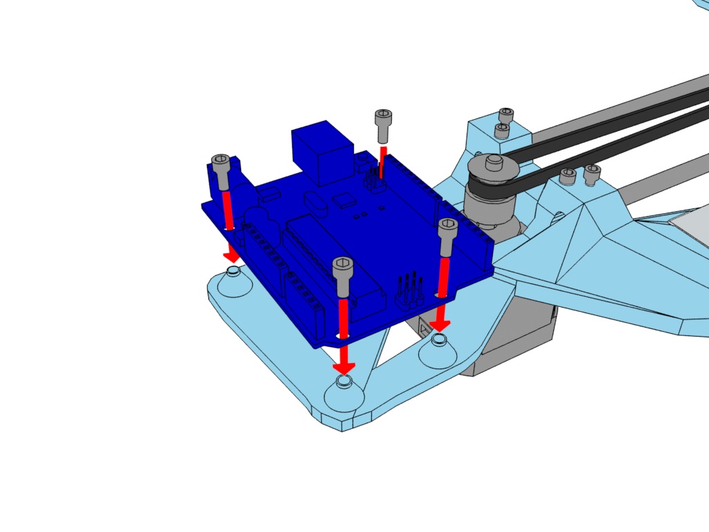
18. Use 4 x M3 6mm screws to hold the Arduino Uno in place.
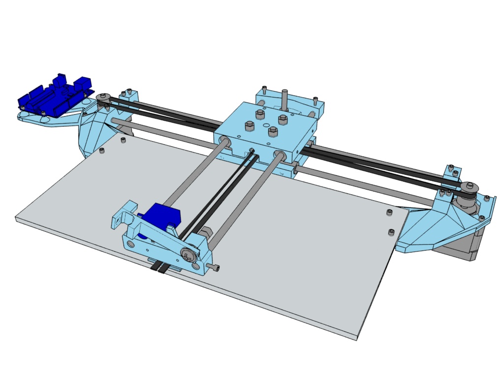
19. The drawing robot is now complete, make sure again that the belt is tight and that the assemblies move freely by rotating the motors by hand.