Goal
Today we will learn how to recieve input from a joystick.
We will later use this to manually control our robot.
Joystick
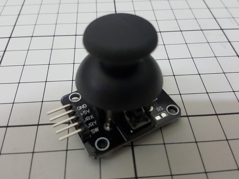
1. Wiring up the Joystick to the Arduino
The Joystick has 5 pins, a 5V pin that connects to the 5V on our Arduino and a GND that connects to the GND on our Arduino.
Next we have the three signal pins, one sends a signal for the joysticks left-right position, we call this X.
The next sends a signal for the joysticks up-down position, we call this Y.
The final pin sends a signal about whether the joystick button is pressed, we just call this one button.
Each of the signal pins needs to connect to its own analog pin eg. A0, A1, A2 etc.
                       // We'll test just the X pin first

                       int x; // This will hold the value for us

                       void setup() {
                         Serial.begin(9600);
                         pinMode(A0, INPUT); // Tell the A0 pin to be ready to recieve a signal
                       }


                       void loop() {
                         x = analogRead(A0); // analogRead(pinNumber) gives us the amount of current going to the pin

                         Serial.println(x); // Send the value of x over the Serial link so we know what it is
                       }
If you upload your code and wiggle the joystick you should get something like the following on your Serial Monitor.
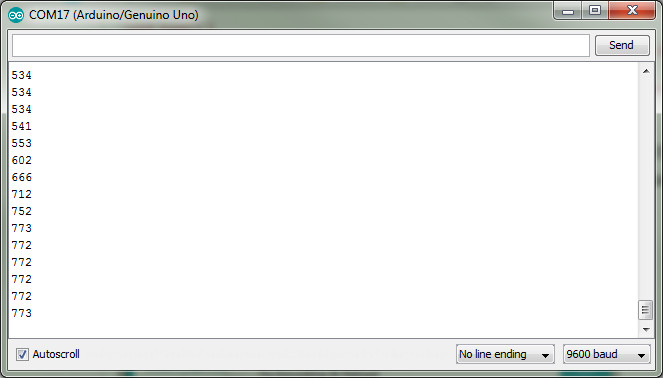
Now that you've got one axis working, set up the code for the y and button pins.
Serial.println() is good for single piece of information but if you want to get several values at once we need to use some Serial.print() commands, Serial.print() does not automatically go to the next line.
                       Serial.print(x);
                       Serial.print("\t"); //"\t" is a special character that signifies a tab
                       Serial.print(y);
                       Serial.print("\t");
                       Serial.println(button); // use println for the last value
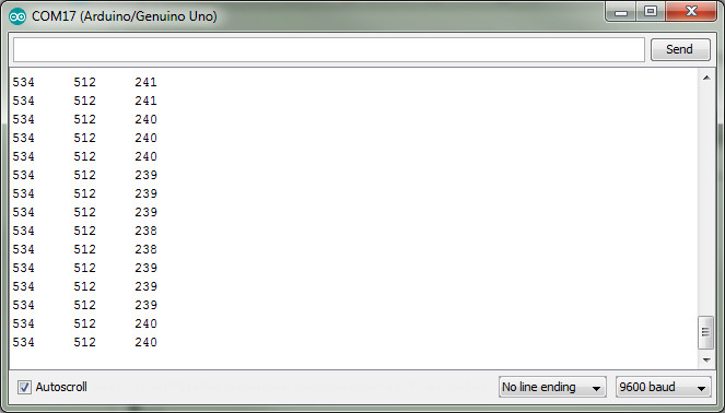
Now we have 3 values, one for x, y, and the button.
When the x and y are centered the value should sit around 512 and can be pushed to a minimum of 0 and maximum of 1023.
The button sits at about 240 and drops to zero when pushed.
Todays Project
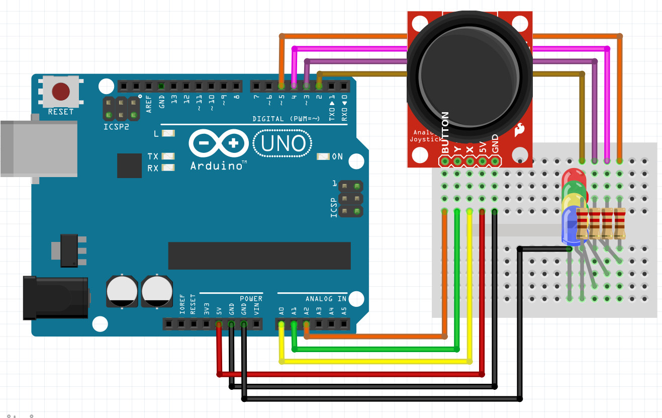
Your mission is to make an invention with a joystick and 4 LEDS (red, green, blue, yellow).
Two of the LEDs will be for x and two for y. eg. When the x is pushed one way the red light is on, when pushed the other way the green light should be on instead.
When the button is pushed ALL the lights should go on.
Hint 1
Each LED is wired into a different digital pin (2, 3, 4 and 5), through a resistor and then back to GND.
The GND pins can all be together and just have one wire going back to the Arduino GND.
Hint 2
                       int x;
                       int y;
                       int button;

                       void setup() {
                         Serial.begin(9600);
                         pinMode(A0, INPUT);
                         pinMode(A1, INPUT);
                         pinMode(A2, INPUT);

                         pinMode(2, OUTPUT);
                         pinMode(3, OUTPUT);
                         pinMode(4, OUTPUT);
                         pinMode(5, OUTPUT);
                       }


                       void loop() {
                         x = analogRead(A0);
                         y = analogRead(A1);
                         button = analogRead(A2);

                         Serial.print(x);
                         Serial.print("\t"); //"\t" is a special character that signifies a tab
                         Serial.print(y);
                         Serial.print("\t");
                         Serial.println(button); // use println for the last value


                         if (button > 10) {
                           if (x < 200) {
                             digitalWrite(2, HIGH);
                             digitalWrite(3, LOW);
                           } else if (x > 800){
                             digitalWrite(2, LOW);
                             digitalWrite(3, HIGH);
                           } else {
                             digitalWrite(2, LOW);
                             digitalWrite(3, LOW);
                           }
                           if (y < 200) {
                             digitalWrite(4, HIGH);
                             digitalWrite(5, LOW);
                           } else if (y > 800){
                             digitalWrite(4, LOW);
                             digitalWrite(5, HIGH);
                           } else {
                             digitalWrite(4, LOW);
                             digitalWrite(5, LOW);
                           }
                           } else {
                             digitalWrite(2, HIGH);
                             digitalWrite(3, HIGH);
                             digitalWrite(4, HIGH);
                             digitalWrite(5, HIGH);
                           }
                       }